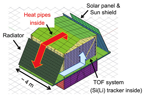
 Conceptual diagram of the thermal system on the GAPS payload.
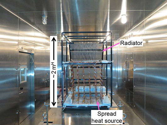 A full-scale engineering model of the thermal system tested in a thermal chamber.
The GAPS thermal system has been newly developed to cool Si(Li) detectors distributed in the tracker. Local heat generated by the electronics on each detector module together with infrared heat inputs from the surrounding ToF system are conducted to heat pipes that are mechanically connected to the detector modules. The heat is absorbed efficiently by a two-phase working fluid contained in the pipe using latent heat. The heat is then transported to a radiator attached to the payload sidewall, which is outside the ToF system and separated from the tracker by more than one meter. The radiator dissipates the heat to space by heat radiation.
The heat pipe is composed of 36 capillary loops connected in series. Every loop crosses 10 tracker layers so that all 360 detector modules are coupled to a loop. By ensuring sufficient cooling of the radiator, passive circulation of the working fluid is generated by the density difference between the hot vapor in the tracker volume and the cold liquid in the radiator. In addition, multiple loops connected in series excite a self-oscillation, which also functions as a driving force for the circulation. These two driving forces operate entirely passively. By optimizing the tube diameter and the fluid material, a highly conductive, low-power, and large-scale thermal system is realized.
In order to make the passive heat-pipe system more robust, some active functions are added based on state-of-the-art thermal control technologies. The saturation temperature of the whole system is controlled by a reservoir. To promote fluid boiling, auxiliary heaters are installed. As a potential backup to assist the flow, a mechanical pump is included. Lastly, check valves are installed to prevent backflow during the cooling of the radiator.
To evaluate the thermal system, scaled-down and full-scale models have been developed and tested in thermal chambers and in stratospheric balloon flights. Dedicated numerical codes to simulate the heat pipe performance have also been developed. The overall temperature distribution of the whole payload is analyzed in parallel using a CAD-based software package. Results from all these tests and analyses indicate that all requirements for the thermal system can be met. Further detailed studies are in progress.